|
|
|
|
|
|
| Return to "24 Bit / 96 kHz Audio ADC and DAC" |
This text is very similar to the text 24 Bit / 96 kHz Audio Analogue to Digital Converter AD2496, because these devices are similar in many aspects.
The circuit diagram of the DA2496 (PDF) shown here is not the latest one. Currently I do not have a newer PDF-version. The details are changing frequently, anyway.
Power Supply
The nominal supply voltage is 12 V DC, but the device works from 8 V on. According to the specification up to 15 V are allowed. The prototype consumes 150 mA.
Analogue: The op-amps are supplied with +/-10 V approx. A LT1054 (100 mA / 15 V capability) generates the negative supply voltage. The voltage followers T1 and T2 furthermore stabilise the op-amps supply voltage.
Digital: A 5 V regulator is employed for the digital section and another low-power 5 V regulator generates the analogue supply and the reference voltage for the ADC.
Digital Inputs
Analogue: The op-amps are supplied with +/-10 V approx. A LT1054 (100 mA / 15 V capability) generates the negative supply voltage. The voltage followers T1 and T2 furthermore stabilise the op-amps supply voltage.
A coaxial and an optical (TOSLINK) S/PDIF input is provided on board. A three pin XLR connector for an AES3 interface may be connected externally through ST2. As requested by the standards, the AES3 input is transformer coupled by a transformer especially designed for digital audio interfaces, but the coaxial S/PDIF input is not.
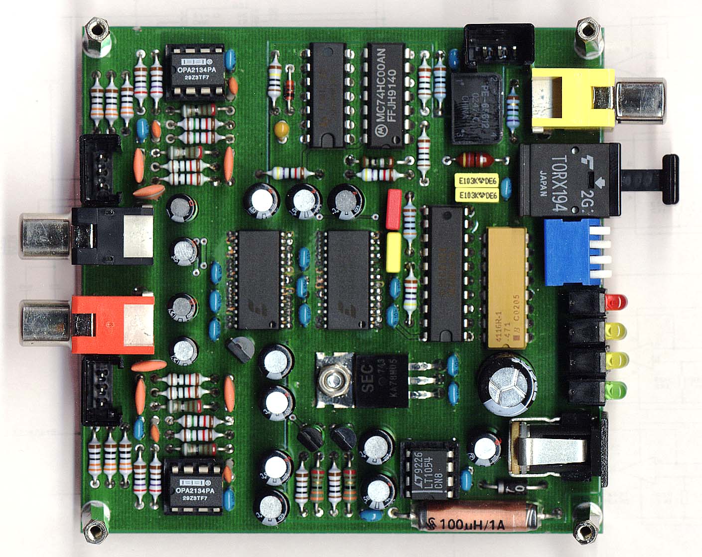
Originally I planned to use the TOTX173 / TORX173 as the optical transmitter / receiver. These are commonly used TOSLINK devices. They work, but I found out later that they are specified only up to 48 kHz sample rate (6 MBit NRZ or 3 MBit bi-phase resp.) and so I had to go for something faster. My distributor recommended TOTX195 and TORX194 as they were available and pin-compatible to the 173s. They are for 5 MBit and industrial use specified which is sufficient. I found out that these devices are much more expensive compared to those for consumer equipment. Now I consider to use TOTX141P and TORX141P which are not pin compatible but for up to 7.5 MBit. However, though they are manufactured in high quantities and thus cheap they are really difficult to buy: Distributors offer industrial types only and consumer devices are directly sold to manufacturers of consumer electronics. See also Toshibas TOSLINK Fiberoptic Devices Overview.
The optical receiver is directly coupled to one of the two input pins of the subsequent S/PDIF receiver. The two electrical inputs must be selected by a switch. They are fed to the other input pin. Electrically this is perfect, but I would prefer either a 3 position input selector switch or all three inputs always in an operational status.
S/PDIF Receiver
The CS8415A S/PDIF receiver operates in hardware mode. This avoids a microcontroller or other circuitry that makes it more difficult for others to reproduce the device. The receiver has a high sensitivity differential input and converts the S/PDIF or AES3 signal into an IIS data stream. The CS8415A may retrieve lots of additional information from the data stream, but in hardware mode this information is available on a limited number of pins only. For experiments I provided LEDs to monitor most of this information. For my experiments this turned out to be very useful and instructive. See the "Set Up and LEDs" chapter below.
For all 4 sample rates the CS8415A reconstructs the 4 different clock frequencies MClk (Master Clock) 8.192 MHz, 11.2896 MHz, 12.288 MHz and 24.576 MHz and the corresponding LRClk (Left/Right Clock), SClk (Serial Clock), and SData (Serial Data) signals.
DAC
The D/A converter CS4396 operates in hardware mode too. . If you want more detailed information please refer to the CS4396 data sheet.
I am very unhappy with the de-emphasis switches: The DAC must be informed about the sampling frequency by two external switches so that the CS4396's de-emphasis filter runs with correct values. This is necessary for signals with emphasis only (which I did not yet experience). The setting of the sample rate switches in case of signals without emphasis does not matter - except for 96 kHz, where both switches must be switched on. Otherwise the system sounds "heavily defective". All this seems confusing. In fact I wondered several times what was wrong again until I got used to these switches. They ought to be removed, either by omitting the de-emphasis capability or by additional logic and, what really makes it complex, a means of determining the sample frequency. A microcontroller would be a relief here, but this is something I wanted to avoid.
In case of loss of input data the S/PDIF receiver's PLL for clock recovery tunes down to some few 100 kHz. This causes a slightly audible noise. The mute input of the DAC does not work in this case and an thus an external mute circuit connected to the Receive Error signal is advisable. I implemented a circuit with just one transistor and one resistor per channel and it works fine.
Output Filter/Amplifiers
The analogue output amplifiers consist of two stages: A low pass filter and - for the balanced output option only - an inverter. XLR connectors for balanced outputs can be connected through ST4 and ST6. An unbalanced output with RCA jacks is on board.
The input filter in the circuit diagram is of 2nd order. It is intended to suppress the high frequency noise coming out of the DAC, far beyond the audible band. I found this remaining noise to be too high: From 300 uV at 96 kHz up to 2.4 mV at 32 kHz. In the prototype I modified the filters to 3rd order ones. Now the noise is reduced to 120 uV or 1.2 mV resp. - this is not a big effect. But the expense of only one capacitor and two resistors resistors makes it worthwhile.
In the prototype I lowered the full scale output voltage at the RCA jacks to 2.21 Vrms or +7 dBV. The level at the balanced outputs should be about 20 dBu (7.75 Vrms), twice as much as it is now. With two additional resistors and some redimensioning this will be possible.
Clock Generation
For all 4 sample rates the CS5361 and the CS8405A need 4 different clock frequencies (MClk), which are generated by the MK1412A from ICS from a standard 14.3181 MHz crystal.
| Sample Rate | Clock Frequency (MClk) |
| 32 kHz | 8.192 MHz |
| 44.1 kHz | 11.2896 MHz |
| 48 kHz | 12.288 MHz |
| 96 kHz | 24.576 MHz |
Set Up and LEDs
| Switch Nr. | Setting | Use | |||||||||||||||||||||||||||||
| 1 | Sample rate in case of emphasized signals |
D. C.: Don't care (ON recommended), N. A.: Not applicable |
|||||||||||||||||||||||||||||
| 2 | |||||||||||||||||||||||||||||||
| 3 | S/PDIF Coax Input | Switch ON in case of coax S/PDIF, OFF otherwise | |||||||||||||||||||||||||||||
| 4 | AES3 Input (XLR Option) | Switch ON in case of balanced AES3, OFF otherwise | |||||||||||||||||||||||||||||
| LED Nr. | Name | Comment |
| 1 | Power On | |
| 2 | Audio | The input data is a straight audio stream (no MP3 or other data) |
| 3 | Original | The source is not a copy (SCMS L bit). Not available (ON) in professional mode. |
| 4 | No Copyright | The source is not protected by copyright law. Not available (ON) in professional mode. |
| 5 | Emphasis | The source audio stream is 50/15 uS emphasized. Not available (or valid) in the 96 kHz mode. |
| 6 | Professional | Professional data format, i.e. no copyright information etc. |
| 7 | Receive Error | Incorrect or no receiver input signal. |
| 8 | Not Valid | Incorrect or no receiver input signal or Validity-Bit (V) is set |
An LED for the U (User Data) bit is missing. The names of LEDs 3, 4 and 5 in the circuit diagram are permuted.
Summary of Advisable Improvements on the Current Prototype
In contrast to the A/D converter the D/A converter needs pretty much rework
* Already modified in the prototype, but not shown in the circuit diagram.
Links to Some Related Data Sheets (updated April, 30th, 2005)
| Manufacturer | Title | Device |
| A/D- and D/A-Converter | ||
| Linear Technology | Switched-Capacitor Voltage Converter with Regulator | LT1054 |
| TI / Burr Brown | High Performance Audio Operational Amplifiers | OPA2134 |
| TI / Burr Brown | High Precision, Low Noise Operational Amplifiers | OPA2227 |
| Texas Instruments | Dual Low-Noise Operational Amplifiers | NE5532 |
| A/D-Converter | ||
| ICS | MPEG Audio Clock Synthesizer (discontinued) | MK1412A |
| ICS | PLL Audio Clock Synthesizer (replacement for MK1412A) | MK2703 |
| Cirrus Logic | 114 dB, 192 kHz, Multi-Bit Audio A/D Converter | CS5361 |
| Cirrus Logic | 96 kHz, Digital Audio, Interface Transmitter | CS8405A |
| Toshiba | Fiber Optic Transmitting Module for Industrial Use | TOTX195 |
| Toshiba | Fiber Optic Transmitting Module for Digital Audio Interface | TOTX141P |
| D/A-Converter | ||
| Cirrus Logic | 24-Bit, 192 kHz D/A Converter for Digital Audio | CS4396 |
| Cirrus Logic | 96 kHz, Digital Audio Interface Receiver | CS8415A |
| Toshiba | Fiber Optic Receiving Module for Industrial Use | TORX194 |
| Toshiba | Fiber Optic Receiving Module for Digital Audio Interface | TORX141P |
| Last update: September, 25th, 2005 | Questions? Suggestions? Email Me! | Uwe Beis |