| |
|
Linear Amplitude and Phase IIR Crossover
A crossover not only with the correct amplitude response,
but also with a perfect pulse and step response
A completely analog design
Also suitable for non-audio applications
| |
|
Linear Amplitude and Phase IIR Crossover
A crossover not only with the correct amplitude response,
but also with a perfect pulse and step response
A completely analog design
Also suitable for non-audio applications
A) I must admit that before I published this article I've never read or heard before about this rather trivial solution for an absolutely linear amplitude and phase IIR crossover, but I could not imagine that this approach has not already been known for a long time and I just happened to miss it. I knew about Linkwitz-Riley crossovers which have a linear amplitude response, but the usual weird phase and step response of other crossovers (except 1st order ones), too.
So thanks to Georg who sent me the link to this Elektor article, Hans who pointed me to the articles from Rod Elliott and Nelson Pass, and E-P Mänd for the hint to Richard Small's most interesting article Constant-Voltage Crossover Network Design from 1969 where he also describes symmetric crossovers, as he calls them.
B) Here I discuss an analog solution, i.e., easily achievable for DIYs. In the digital domain other solutions exist, with advantages and disadvantages, but at least by far not as easy to understand and build as this.C) Electronics technicians often talk and discuss about "frequency responses", but they often seem not to be aware of that they actually mean "amplitude responses". A frequency response is a complex thing, and I don't mean it in the sense of "complicated", but purely mathematically: A frequency response consists of the
Only both of these responses define the behavior of a (linear) system completely.
The frequency response defines a system in the frequency domain, the step or impulse response does the same in the time domain.
For example, the Linkwitz-Riley crossovers: While they feature the wanted linear amplitude response where all frequencies pass through the outputs so that when they are added (electronically or acoustically) with each other, in the sum each frequency has the original amplitude. But in the time domain, when you apply a square wave signal to this crossover, the sum of the output signals looks unbelievably distorted. Here, for example, is the pulse response for a single 10 ms square pulse filtered by a 3-way (300 Hz, 3 kHz), 4th order Linkwitz-Riley crossover:
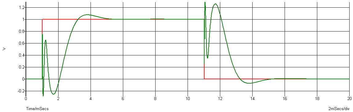
Fig.: Sum Output Step Response of a 4th order Linkwitz-Riley Crossover (Click to enlarge)
The output signal (green) should be the same as the input signal (red). Would you believe that the actual output signal can still sound normal? Yes, it can: The human's ear is not very sensitive to phase errors, but it still is. But is this technically satisfying?
Non-Audio: Even though it is predominantly interesting for crossovers for loudspeakers there may be other applications where analog signals are to be send over several channels, each with limited bandwidth, like it is the case in loudspeakers. For example, a long time ago I thought about galvanic decoupling a very wide-band analog signal with transformers. The bandwidth was too high to use just one transformer, so I thought about one transformer designed for the low and another one for the high frequencies. Even though an active 1st order crossover would do the job there, too, this might also have been a solution.
As mentioned, my idea for a solution for a crossover with a correct frequency response (amplitude and phase) is quite trivial:
The traditional approach, e.g. for a 2-way crossover, is a low- and a high pass filter for each branch, preferably dimensioned so that the sum of both output signals for each frequency is the same as the input signal itself:
UOut = UOut_L + UOut_H = UIn
Unfortunately with two separate filters that is not trivial, at least impossible with simple low- and high-pass filters. But what when you use just any more or less usual filter, any low- or high-pass filter for example, and build the difference of the input signal and the filter's output:
UOut_H = UIn - UOut_L ?
Because for e.g. low frequencies the LPF's output signal is the same as the input signal (amplitude and phase), the difference for low frequencies must be zero. That's what you need for a high-pass filter. So, instead of an extra HPF, you just need a difference amplifier. It should work with any crazy low- or high-pass filter, because when you add both signals again, the sum is by design equal to the input signal.
UOut = UOut_L + UIn - UOut_L = UIn !
This also works for high-pass filters, where the difference between the input and the output signal is zero for high frequencies.
This principle is easy to simulate. For the following simulation I used 4 different 3rd order high-pass filters:
In my simulator I can directly use Laplace functions, e.g., for filters (LAP1 to LAP4), but also to build differences (LAP5 to LAP8):
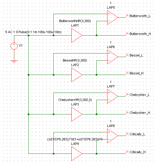
Fig.: Simulation Setup for 4 Different Filter Characteristics
Let's have a look at the results and discuss what can be observed.The graphs do not show the total output signal, i.e., the sum of the HPF's and the difference amplifier's outputs, because it's too trivial: I swear, it is really identical to the input signal.
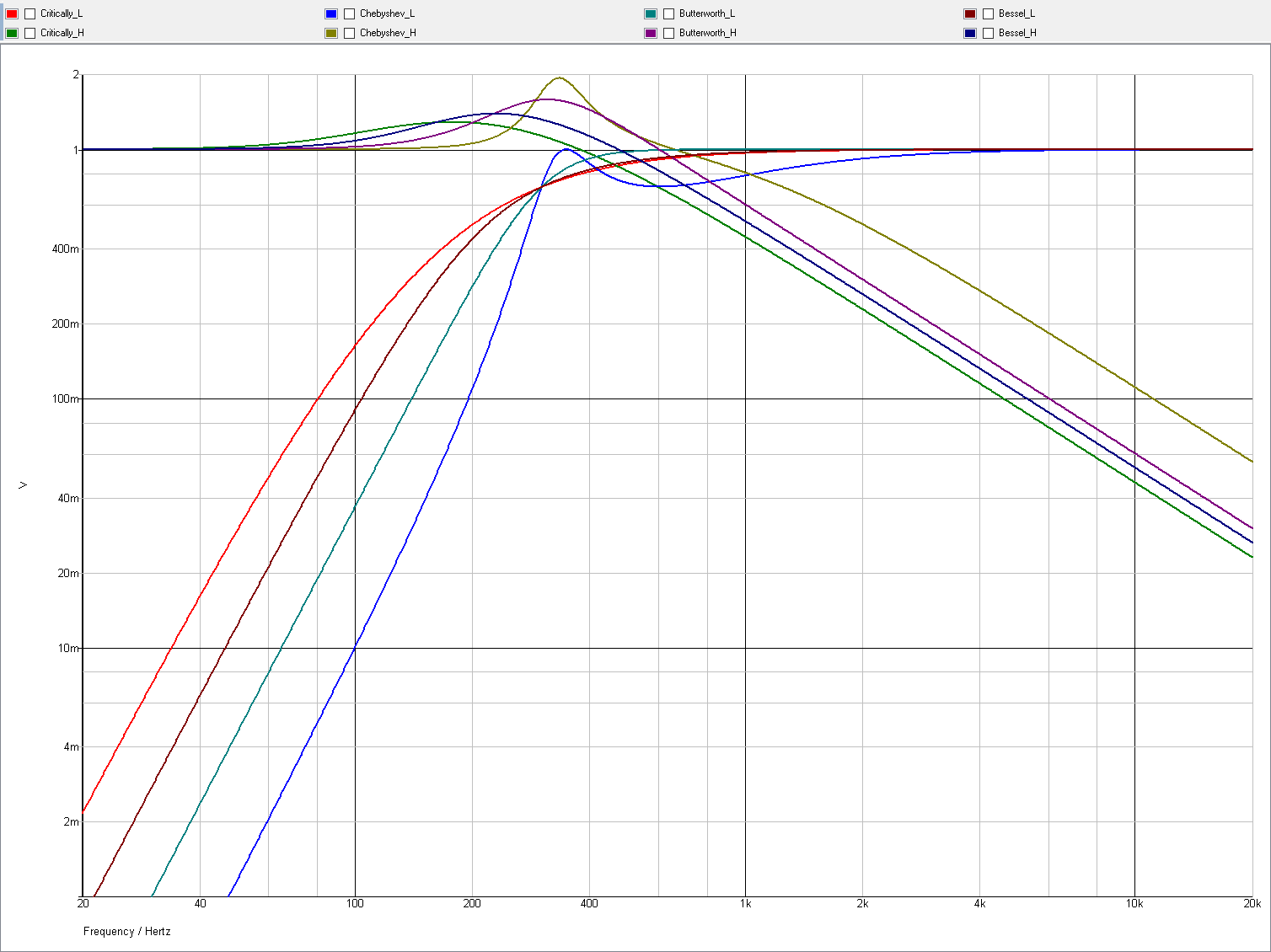
Fig.: Low- and High-Pass Output Amplitude Responses for 4 Different High-Pass Filter Characteristics (Click to enlarge)
I aligned the HPF's corner to 300 Hz at -3 dB. Currently the Critically Damped filter tweeter gets the most, the Chebyshev filter tweeter gets the least power, and for the woofer it is reversed. An alignment so that the tweeter gets almost the same power with all filter characteristics would make more sense.
What is eye-catching is that the amplitude response of the difference amplifier's output which replaces the LPF output, has a slope of -6 dB/octave only. This is true for any other HPF order, too(!). Also, when you use an LPF with any order instead of an HPF, the slope of the amplitude response of the difference amplifier's output is +6 dB/octave. (It should be easy to prove that mathematically by solving the transfer resp. Laplace function for the difference amplifier's output signal and find out that the nominator's degree is always one less than the denominator's degree.) See also further below.
In practice this means that one of the speakers gets more of the signal of the other one than vice versa. It is advisable to use an HPF because a woofer can easily cope with the little more power that, due to the shallow slope, comes from the higher spectrum. With an LPF, the tweeter would get much more power from the lower spectrum, and that should be avoided.
Another less obvious, but possibly more important fact is that the lower frequency channel has much influence within the lower frequency range of the higher frequency channel. The crossover frequency, i.e., the frequency, where both outputs carry the same level, is no longer at the -3 dB or -6 dB point of the filter(s). Instead, due to the overshoot in the amplitude response, it is way beyond the filters' corner frequencies. E.g., for the 300 Hz Butterworth filter above, the actual crossover frequency is about 550 Hz. Conclusion: The speakers frequency responses should overlap more than usual.
Last, but not least, within a small region below the corner frequency, the lower frequency channel needs up to twice as much power in order to keep the whole system's amplitude response linear.
Finally let's have a look at the simulated step responses:
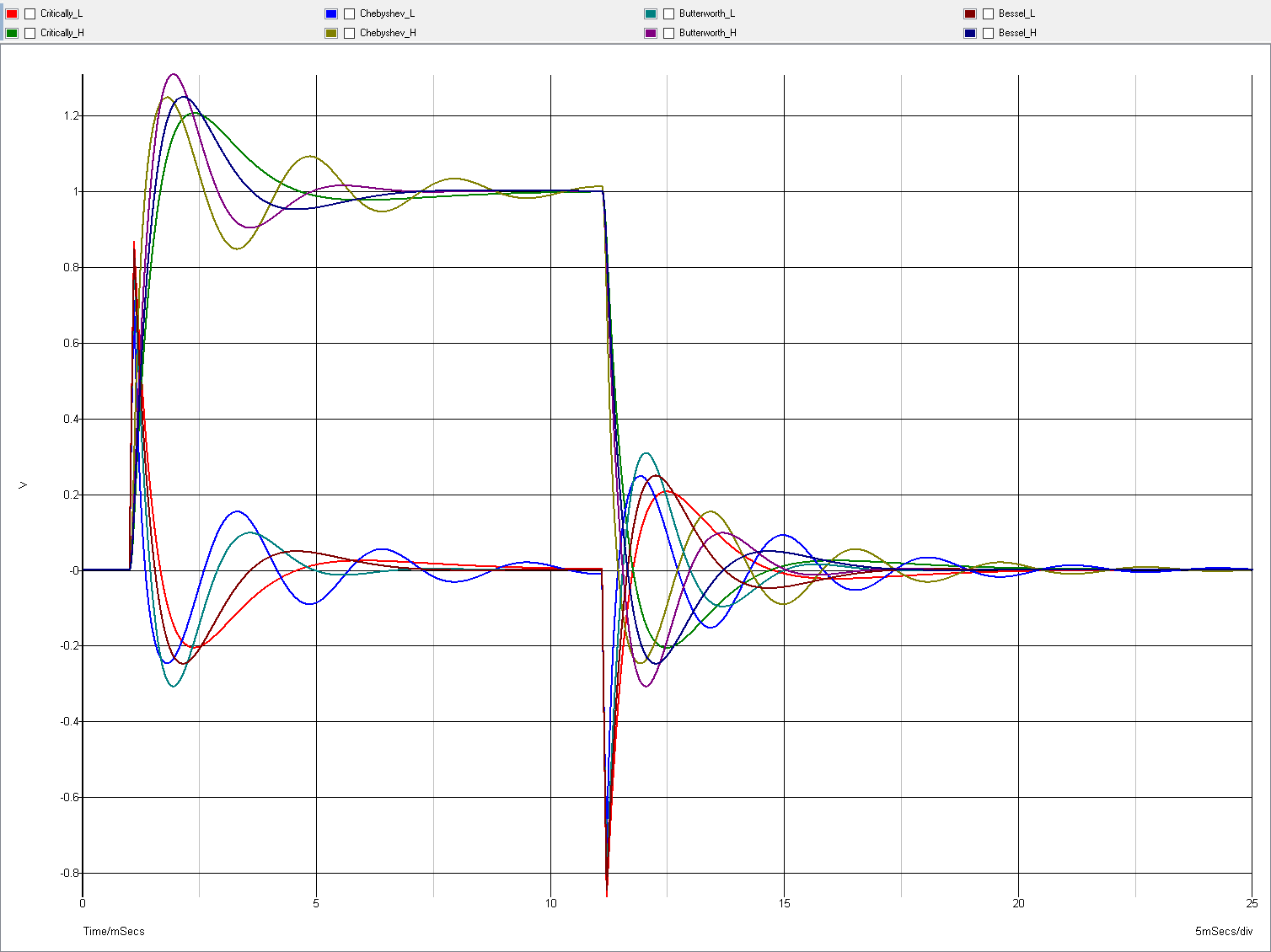
Fig.: Low- and High-Pass Output Step Responses for 4 Different High Filter Characteristics (Click to enlarge)
There is no surprise. It is obvious that the sum of the corresponding signals form the original 1 V, 10 ms square pulse applied to the input. Different filters do not change the results significantly. Would I implement such a crossover, I would choose a filter with little overshoot as well in the amplitude as in the step response. I.e., a Critically Damped or a Butterworth high-pass filter.
Just to gain a little experience, let's have a look at a design with a 1st, 2nd, 3rd and 4th order 1 kHz Butterworth low-pass filter:
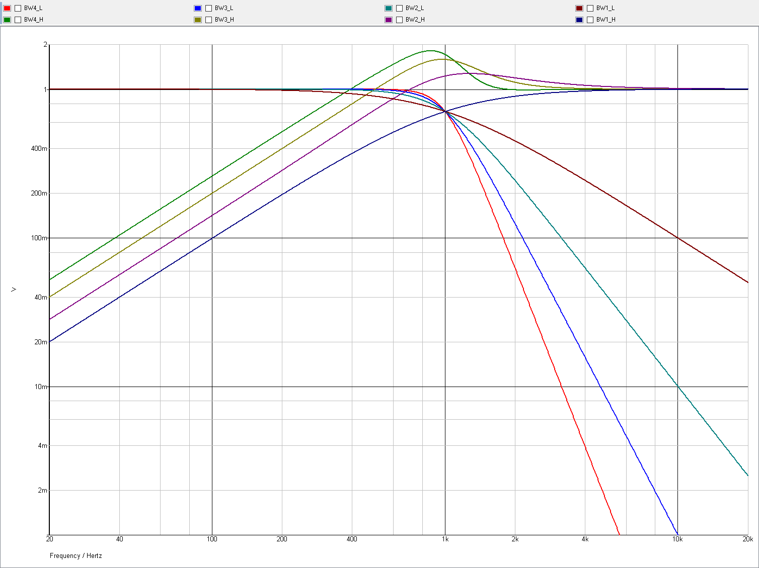
Fig.: Low- and High-Pass Output Amplitude Responses for 4 Different Low-Pass Filter Orders (Click to enlarge)
As mentioned above, all of them exhibit +6 dB/octave for the difference signal (= high-pass output).
Finally, a 3-way crossover is easy, too. In this case I used two 3rd order Butterworth high-pass filters of 300 Hz and 3 kHz:
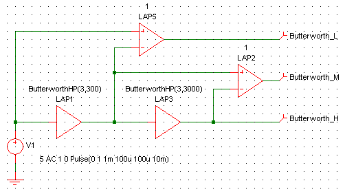
Fig.: Simulation Setup for a 3-Way Crossover
Again, the amplitude responses bare no surprises. 18 dB/octave for the high-pass slopes, -6 dB/octave for the low-pass slopes:
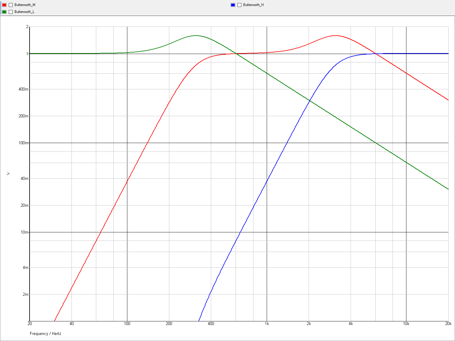
Fig.: Low-, Band- and High-Pass Output Amplitude Responses for the 3-Way Crossover (Click to enlarge)
I provide a circuit diagram here in case you want to make a quick experiment and don't want to care about filter dimensioning and so on.
It shows the 3rd order Butterworth high-pass filter based 3-way crossover with crossover frequencies of 300 Hz and 3 kHz as described in the chapter above. You can use it as a 2-way crossover, too, by omitting the components for the 3-way outputs. You can scale the crossover frequencies simply by scaling the capacitors, e.g., 10 nF for ~ 1 kHz.
| Last update: January 7th, 2020 | Questions? Suggestions? Mail Me! | Uwe Beis |