MPX-AZIO:
Fast and Meaningful Azimuth and
Orthogonality Measurement
on Pickups using Synchronous Rectification and a Multiplex Method
( Deutsche Version: Schnelle und aussagekräftige Azimut- und
Orthogonalitäts-Messung an
Deutsche Version: Schnelle und aussagekräftige Azimut- und
Orthogonalitäts-Messung an
Tonabnehmern mittels Synchrongleichrichtung und einem Multiplex-Verfahren)
Content
Preface
The advantage of this measuring method:
With the MPX-AZIO, the correct measurement value for both the azimuth and the orthogonality of the pickup is determined immediately, in real time, without prior calibration or channel selection. Within seconds, measurements can be taken at various points on a test record, for example, and experience can be gained as to how to make the optimum adjustment. With a simple measuring device this would only be possible with great effort.
It has been shown in practice that track error angles cannot simply be measured at one point on a test record and then assumed to be the same for the rest of the record. Such values depend on many influences, but if only a simple measuring method is available, with which relatively cumbersome only a single, temporally and locally limited measured value can be determined, only with great effort can experience be gained how the conditions are under other circumstances. In addition, simple measuring devices only determine the level of the crosstalk signal and thereby rumble and noise as well as non-phase-synchronous crosstalk is erroneously included.
This text describes the way to the development of a
measurement method for determining the azimuth and orthogonality error of
pickups on turntables.
Some basic principles are explained, from which knowledge is gained and conclusions are drawn.
Based on this, a prototype for this measuring method was developed, with which also some exemplary measurements were carried out and documented here.
The method or the prototype is currently called
MPX-AZIO.
Introduction
Channel separation in stereo records is achieved by recording the two channels separately on each of the two edges of the groove arranged at a 90° angle. Pickup systems must
separate these channels as well as possible, i.e. each of the subsystems must ignore movements from the other flank as completely as possible.
 To accomplish this, the subsystems must be aligned correctly.
Mainly, each subsystem must be exactly at a 90° angle to the orientation of the other flank of the groove of the record.
To accomplish this, the subsystems must be aligned correctly.
Mainly, each subsystem must be exactly at a 90° angle to the orientation of the other flank of the groove of the record.
While the alignment of the subsystems at a 90° angle to each other, i.e. their orthogonality, is production-related and cannot be influenced by the user, with high-quality tonearms, the alignment of the entire pickup, called the azimuth, can often be adjusted by turning and thus optimized.
In the simplest case, the azimuth can be adjusted by optical aiming. But more precise and meaningful is a determination of the azimuth with a suitable test record and a measuring device with which the crosstalk to the other channel is measured. In this method, for example, the manufacturing-related azimuth and orthogonality errors are more or less accurately detected.
For this metrological optimization of the azimuth setting
the two crosstalk values (Left → Right
and Right → Left) are determined. If they are identical (and ideally even 0), the setting is considered optimal. If they are not identical, it is attempted to reach this state by gently turning the pickup head (the headshell).
This is all quite simple in theory, but not in practice. On the one hand, the simple measuring method does not necessarily only determine the crosstalk caused by the angle errors, because the sound recording on a record does not function ideally enough. On the other hand, the procedure of measuring two values from two different tracks is quite cumbersome.
Here a method is presented, in which
1. the crosstalk is determined phase-correct by means of synchronous rectification, and
2. with multiplexed signals and double scales both measured values are determined with only one measurement and are conveniently stored and displayed until the next comparison.
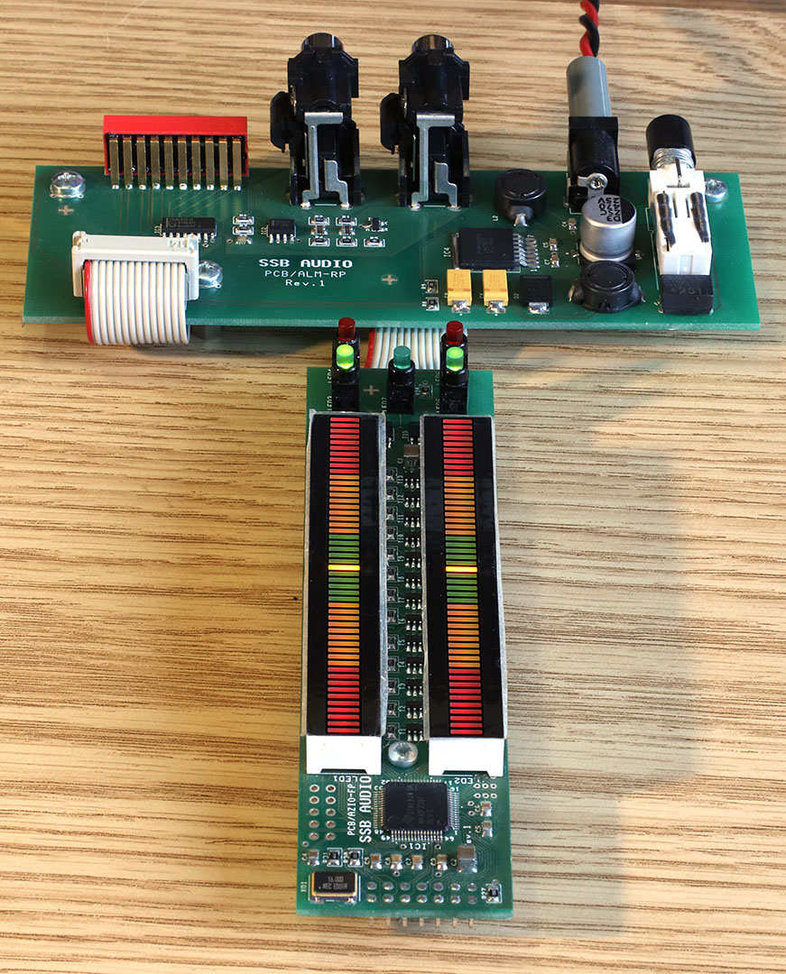
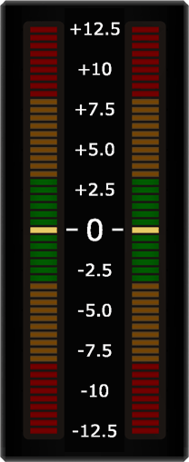
This process has been realized with a fully functional prototype. The prototype has two 3-color LED bargraph displays with 51 LEDs each, which can display crosstalk in the range from -12.5% to +12.5%, as well as another 5 LEDs for status indication. It can be demonstrated with a normal test record, but without the advantages of the multiplex method. At the moment there is no suitable test record for the multiplex procedure, therefore a "test record simulator" was built, with which among other things the signals can be generated, which would be present on a corresponding test record. With the test record simulator, azimuth and orthogonality errors can be variably adjusted, but otherwise it works ideally, i.e. other errors that occur during record playback are not simulated.
|
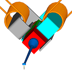
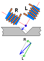
The picture on the left shows a correct setting of azimuth and orthogonality. The two coils are at a right angle to each other and at a 45° angle to the record surface.
With the mono signal of this example, the needle moves
horizontal to left (blue arrows) and the coils detect movements in the directions marked by green arrows.
The vector diagram shows how the horizontal movement is divided into two movements that go into the coil directions.
|
|
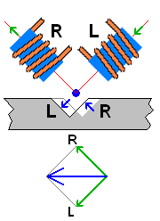
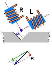
In this picture the azimuth is wrong, the pickup is turned to the left. In addition, only the left channel of the record carries a signal.
The vector diagram shows how the diagonal movement to the bottom left (blue arrows) is divided into two movements going in coil directions (green arrows): The left channel still gets almost the full signal. A small signal crosses over to the right channel. In this case, it cross-talks with the same direction of movement (or phase) as with a mono signal, because in both cases the magnet moves towards the coil of the right channel.
|
|
Also in this picture the azimuth is wrong, but the pickup is turned to the right. Also here only the left channel of the record carries a signal.
The vector diagram now shows that here, too, a small signal cross-talks to the
right channel. But in this case, it cross-talks with the opposite direction of movement (or phase), because the magnet moves away from the right coil of the right channel.
|
As long as the angle is small, each degree of misalignment produces approximately 1.7% crosstalk, or each percent crosstalk is caused by a misalignment of approximately 0.57°. Typical crosstalk values of -20 dB = 10% would therefore be caused by an angle of approx. 5.7° if they were based exclusively on an incorrect angle setting.
For the sake of completeness, it should be mentioned that there are orthogonal errors
also with radial tone arms because of their function-related horizontal
misalignment angles. Only in two places, at radii 66 and 121 mm (according to IEC standard) the horizontal misalignment angles are 0, in the rest of the range they can grow up to approx. +/‑1°. However, the orthogonality errors of less than 0.01° can be neglected. The same also applies to the vertical tracking angle (Vertical Tracking Alignment, VTA).
It can be summed up:
If the azimuth setting is incorrect, crosstalk will occur, depending on the direction of rotation:
- on the channel that is rotated outwards or downwards with the same phase and
- on the channel that is rotated inwards or upwards with the opposite phase.
This also allows the crosstalk between the two
channels, which is caused by faulty orthogonality, i.e. when the coils are not exactly at an angle of 90° to each other:
- At angles greater than 90° it occurs on both channels with the same phase and
- at angles smaller than 90° it occurs on both channels with the opposite phase.
Besides, actually, it's not important how the
coils are aligned. Much more important is the field line of the magnet and the alignment of the pole shoes not shown here, which are ultimately decisive for the correct angle. The unavoidable inhomogeneities of the magnetic fields also play a major role here, but this leads too far.
It should be pointed out once again that crosstalk is not only caused by incorrect angle settings. However, it can be assumed that crosstalk, which occurs due to incorrect angle settings, occurs practically exclusively either in phase or in counterphase with the signal of the other channel. The experiments showed that harmonics with double the fundamental frequency and constantly changing phase played a significant role. Measurement methods that only consider the magnitude of the signal, but not its phase and also not the spectrum of the signal, are obviously suboptimal.
It is therefore recommended to use a measurement method that takes into account the phase of the signal on the channel to which crosstalk occurs, e.g. by multiplying the source signal, i.e. the signal of the channel carrying the signal, by the signal of the channel without signal (synchronous rectification). The crosstalk attenuation results from the ratio of the mean time value of the product to the mean time value of the square of the source signal:
This block diagram shows the core of the measuring procedure,
realized with analog means. The MPX-AZIO, on the other hand, works purely digitally.
Only portions of the crosstalk signal that are positive or negative
in phase with the test signal are detected by synchronous rectification. Also the observed spectral components with twice the frequency of the test signal as well as rumble and noise are ignored.
To determine the crosstalk signal a multiplier + low pass filter, i.e. the pure synchronous rectification of the above block diagram, would be sufficient. In this case, however, the level of the measurement tone would have to be defined before each measurement, or the level of the crosstalk signal would have to be divided by the level of the measurement tone after each measurement. Due to the more complex procedure used here, such a calibration is not necessary.
To make measurements with the MPX-AZIO even more convenient and faster, two separate scales are provided. In addition, the procedure automatically detects:
- Which signal is the stronger one,
- whether the stronger signal is strong enough,
- whether the stronger signal is not overdriven and
- whether the weaker signal is plausibly smaller than the stronger signal.
If these requirements are met, the measured values are output via a low-pass filter on the respective scale. As long as these prerequisites are not fulfilled, the last display value reached remains frozen. Of course, this does not only apply if no measurement is made at all, but also for the channel that is currently carrying the stronger signal, i.e. while crosstalk is being measured on the other channel.
Because of this automatic changeover, it is sufficient to use a test signal for a moment to measure one and then for a moment to measure the other crosstalk and only then to read off the values of the azimuth and orthogonality settings on the double scale:
|
|
|
|
|
The ideal case:
In the ideal case, i.e. with a perfect pickup, both measured values are 0.
|
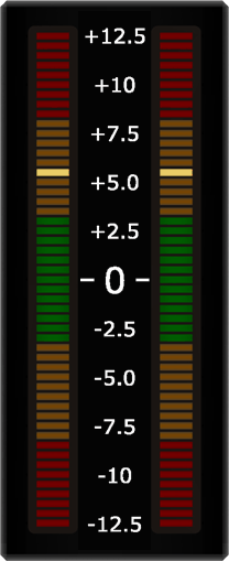
Azimuth error:
In the case of a pure azimuth error, both measured values are of equal size, but have different signs.
|
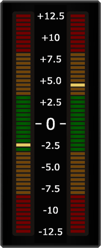
Orthogonality error:
In the case of a pure orthogonality error, both measured values are equal and have the same sign.
|
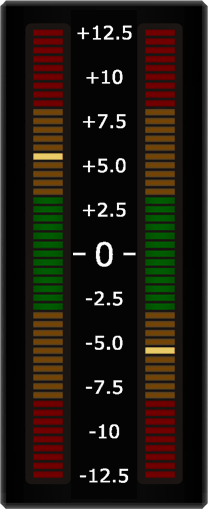
Real measurement:
In a real measurement, there will probably be both an azimuth and an orthogonality error.
|
In practice, however, measured values from a record are not stable. They fluctuate more or less around an average value, but more about that later. It is up to the observer to draw conclusions from these fluctuations regarding improvement possibilities, strengths, weaknesses and errors of the system.
It makes sense to immediately use the automatic assignment of the configuration of the input signals for another convenience function: If the signal on the test record is already constantly changing between right and left, i.e. if it is multiplexed, both crosstalk measured values can be displayed simultaneously. It is then no longer necessary to provide two separate recordings for left/right and right/left measurement and to place the pickup alternately into one and the other track.
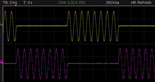
 A corresponding test record does not exist yet. Because of this, and because it's clearer, the following oscillograms were generated with the "test record simulator". So they do not reflect the more complex, unsteady reality.
|
The ideal case:
In the ideal case, i.e. with a perfect pickup, both crosstalk signals are 0.
|
|
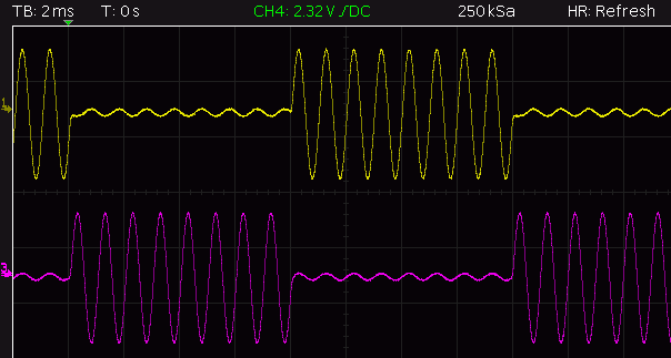
Azimuth error:
With a pure azimuth error, both crosstalk signals are of equal size, but have different signs.
|
|
Orthogonality error:
In the case of a pure orthogonality error, both crosstalk signals are equal and have the same sign.
|

|
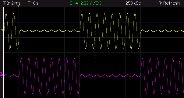
Real measurement:
Real crosstalk signals are likely to have both an azimuth and an orthogonality error.
|
In the MPX-AZIO, especially for the multiplex measurements, it is ensured that the signals which are disturbed in the switching moment have no influence on the measurement results. For this purpose, all measurement results that occur for a sufficient time before and after the signal change, are ignored. In practice, multiplex frequencies of approx. 30 Hz have been well proven, i.e. there are packets of 16 1 kHz oscillations each alternately on the two channels. In the above oscillograms, packets with 8 1 kHz oscillations each with a multiplex frequency of approx. 60 Hz are shown for better recognizability.
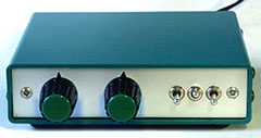
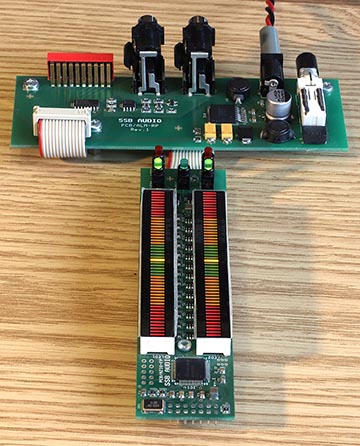 The prototype is built on the hardware of the ALM and
extended with additional LEDs for signaling the operating status.
The prototype is built on the hardware of the ALM and
extended with additional LEDs for signaling the operating status.
Hardware features:
- Input: 2 cinch socket pairs connected in parallel
- Display of the measured value with 2 LED bars with 51 3-colored LEDs each
- Signaling of the operating status with 5 LEDs
- 12 V operation
Functions:
- Check and display with one red LED each that the maximum levels are not exceeded, i.e. that none of the inputs are distorted.
- Check and display with one green LED each that a measuring tone with a sufficient input level is present at a channel. The input level must be at least 1% of the maximum level (-40 dB FS, i.e., the dynamic range is 40 dB).
- Check and display with a green LED that the signal of the other channel is at least ‑10 dB below that of the measurement tone.
- Determination of the crosstalk signal by synchronous rectification.
- Calculation and acceptance of a measured value only if the above conditions are met and if the level of the measurement tone is largely constant at least 2 ms before and 2 ms after.
- Calibration before measurement is not necessary because
the crosstalk is calculated directly even at different signal levels.
- Display range linear from +12.5 to ‑12.5%. The resolution is 0.5% per LED. I.e., the smallest crosstalk displayed with only one LED is ‑46 dB and the full scale is ‑18 dB.
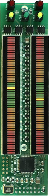
If, as in the photo, the top left and the middle
green LED lights up, the left channel carries the measuring tone and crosstalk to the right channel is displayed on the right scale.
So at the moment of this recording, there was a crosstalk with
negative phase to the right channel and a slightly lower crosstalk with positive phase to the left channel measured before.
The measurement results obtained with such azimuth measurements
are, due to the electromechanical storage, by their very nature not very stable and reproducible. There are an enormous number of influencing factors on the crosstalk. You can't expect perfect results, but it's obvious that the azimuth setting can be optimized. In particular, it is valuable to gain experience with many measurements under different circumstances. However, this is of course not as easy with cumbersome measuring instruments as with a measuring instrument that offers an almost instantaneous display of a pair of measured values, as it was realized in the MPX-AZIO.
Two measurements on two different turntables are shown here as examples.
The first is a Lenco L75 with a Shure M 95 G, the second is a Revox B291 with a short tangential arm and an ELAC D796 H30. Unfortunately both do not allow azimuth adjustment.
The test record is a "Clearaudio Frequency Test Record CA-TRS-1007", which is mainly intended for frequency response measurements, but also contains two tracks with 10 seconds 1 KHz each on the left and right channel. Both sides of the record are the same, so that there are at least two physically different recordings of the same test tone sequences.
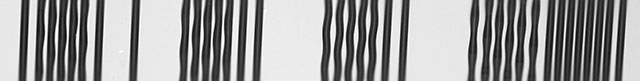
Picture: Section of the test record, from left to right: 1 kHz only left, 1 kHz only right, 1 kHz in phase, 1 kHz opposite in phase, empty grooves. The centre of the record is on the right. The left channel is recorded on the inner flank.
These test tone sequences were played several times one after the other by both turntables and recorded on a PC with Audacity. There is a recording of each turntable and each turntable side for which the test tone sequence with the 1 kHz tone was played 10 times in a row, first on the left, then on the right channel. Although these multiple playback operations actually took place under identical conditions
they are quite different from each other. It is important that recordings of such different playback processes are reproducibly available on the PC.
A 29 seconds long excerpt (slightly more than a test tone sequence) of two of these recordings with Audacity is shown here (graphically revised for the sake of clarity afterwards):
The two upper tracks contain the signal from the L75, the
lower from the B291. The upper channel is the left one.
The vertical scaling ranges from just +0.03 to ‑0.03,
corresponding to a gain of approx. 30. This makes crosstalk clearly visible, but the measuring tone goes far beyond the scale range.
After the needle has been placed, the rumbling and the
snap into the groove can be recognized, then you see two sequences of about 10 seconds, separated by a few seconds of empty groove.
In the first sequence you can see the full amplitudes on the left channels, which of course are distorted in the display. Crosstalk to the right channels can be seen below. In the second sequence it is the other way round.
The recorded signal approximately represents the mean value or
the magnitude of the amplitude of the pickup. It can therefore never become zero or negative, as opposed to the measurement made with the MPX-AZIO.
Already the L75 shows a strong crosstalk here on the right and a weaker one on the left channel. The B291 shows a stronger crosstalk on the left channel, but this varies considerably synchronously to the rotation of the turntable. It could be that this effect is related to a considerably higher sensitivity of the pickup to height variations or centering errors of the record due to the very short tonearm.
The results with the MPX-AZIO could best be shown with a film or a practical demonstration, but here two oscillograms must suffice. For this purpose the prototype of the MPX-AZIO was modified in such a way that it could output its measurement results as an analog value for oscillography.
The 0-lines are approximately at the arrows visible at the left edge, the scaling is approx. 3% per scale division.
|
The L75 shows a moderate crosstalk with positive phase from R → L (top).
The crosstalk L → R (below) is considerably stronger and with negative phase.
Both signals fluctuate slightly with the double speed of the turntable.
Conclusion: The azimuth could be slightly optimized, but a small orthogonality error would remain.
|
|
The B291 shows a stronger crosstalk from R → L (above), which usually remains in the negative range, but fluctuates very strongly synchronously with the rotation of the turntable.
The crosstalk L → R (below) is very small and mostly very slightly negative.
Conclusion: The azimuth could be optimized, the remaining orthogonality error would also be small, but the fluctuations are very disturbing.
|
The signal characteristics underlying such extreme fluctuations are correspondingly adventurous, as the following oscillogram shows:
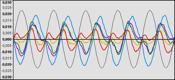
It's from a sequence with the crosstalk of the B291
of → L and contains 5 cut-outs over 5 ms, which were created within only one revolution of the turntable. The thin black line is the test signal on the right channel,
reduced in amplitude by a factor of approx. 20. The blue line generates the strong crosstalk with negative phase, the red line the weak positive crosstalk. Obviously, harmonics with double fundamental frequency with constantly and rapidly changing phase play a significant role. The suspicion suggests that this comes from the adjacent groove. On the other hand, it should also be visible in the signal of the L75, unless its needle is deeper in the groove... So there is a lot of room for speculation.
Finally, it should therefore be pointed out once again that the measurements are not very reproducible. If the same track is played twice directly one after the other, differences are already clear to see. If the circumstances change only slightly, e.g. if the record is put on again, the differences are greater. The two actually identical recordings on both sides of the test record still showed similar results, but also larger differences. The crosstalk will also depend on the position at which the test signals are on the record. Simple measurements, which are only based on the signal strength in the other channel, are not very helpful under these circumstances, but with the synchronous rectification method used in the MPX-AZIO, an azimuth setting can be much better detected and corrected.
| Last update: October 28th, 2020 |
Questions? Suggestions? Mail me! |
Uwe Beis |