| |
|
DS1kGen - Precision 1 kHz Audio Sine Wave Generator
| |
|
DS1kGen - Precision 1 kHz Audio Sine Wave Generator
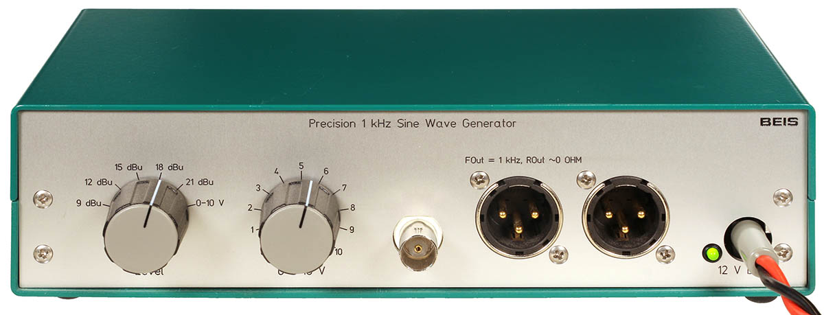
This is a delta sigma based analog 1 kHz sine wave generator with the main intention to generate a precise 1 kHz tone for calibration of analog level meters. Thus I laid the emphasis on a constant and precise output voltage. Here I describe the circuit diagram and the sine wave generating microcontroller's firmware.
This is actually not meant to be a DIY project, but should anybody be interested in reproducing it, I can hand out the Gerber and Excellon files for the PCB and the hex and possibly even the source code for the µC. It is not too difficult to reproduce this device.
I don't specify the precision of the level, because I simply have no means to measure it as precise as I would like and ought to. I own a quite good but old multimeter, a Hameg HM8112-2, which displays up to 6½ digits even in AC-ranges and was originally specified with an error of less than 0.3% of reading + 0.1% of full scale in the here relevant AC-ranges of 2 VRMS and 20 VRMS. I compared it to a probably much better Agilent 34410A multimeter. Both matched well or even clearly within these specified values. I assumed the Agilent 34410A to be better calibrated than my HM8112 and calibrated the generator using the correction factor I got from the comparison. Thus I hope to have achieved a precision of about 0.1%.
 The sine wave is generated by a microcontroller, a simple and cheap TI MSP430F2011. The sine wave "leaves" the µC as a delta sigma bitstream. This bitstream is low-pass filtered in order to remove the quantization noise, divided either in 5 steps of 3 dB or with a potentiometer from 0 to 10 VRMS. Finally it is amplified and converted to a balanced signal for the XLR outputs. So far there is nothing exotic (except probably the delta sigma sine wave generator), but the details are important.
Because the generator should neither have a direct (galvanic) connection to its enclosure nor to the external power supply, I used a DC-DC converter with floating outputs for the internal ±12 V supply. This also allows that the BNC connector's ground is connected to the negative line of the balanced outputs.
The µC's bitstream's 1st order modulator clock frequency is 800 kHz and it is modulated by the 1 kHz sine wave with a modulation index of 90%. The reason for these 90% instead of 100% is declared later. Because the analog (and thus reference) levels are the µC's power supply rails of 0 and 3.3 V, the 1 kHz signal has an approximate value of 2,97 VPP resp 1.05 VRMS.
The µC's bitstream output is directly used as an analog signal, i.e., there is no extra 1-bit digital to analog converter provided. Thus the µC's power supply must be precise. I provided a simple 3.3 V source with a TL431 as reference and alternatively an improved (and of course more expensive) 3.3 V source using the ADR4533A. The ADR4533A features typically 4 ppm/°C and 25 ppm/1000 h. The ADR4533B is even better.
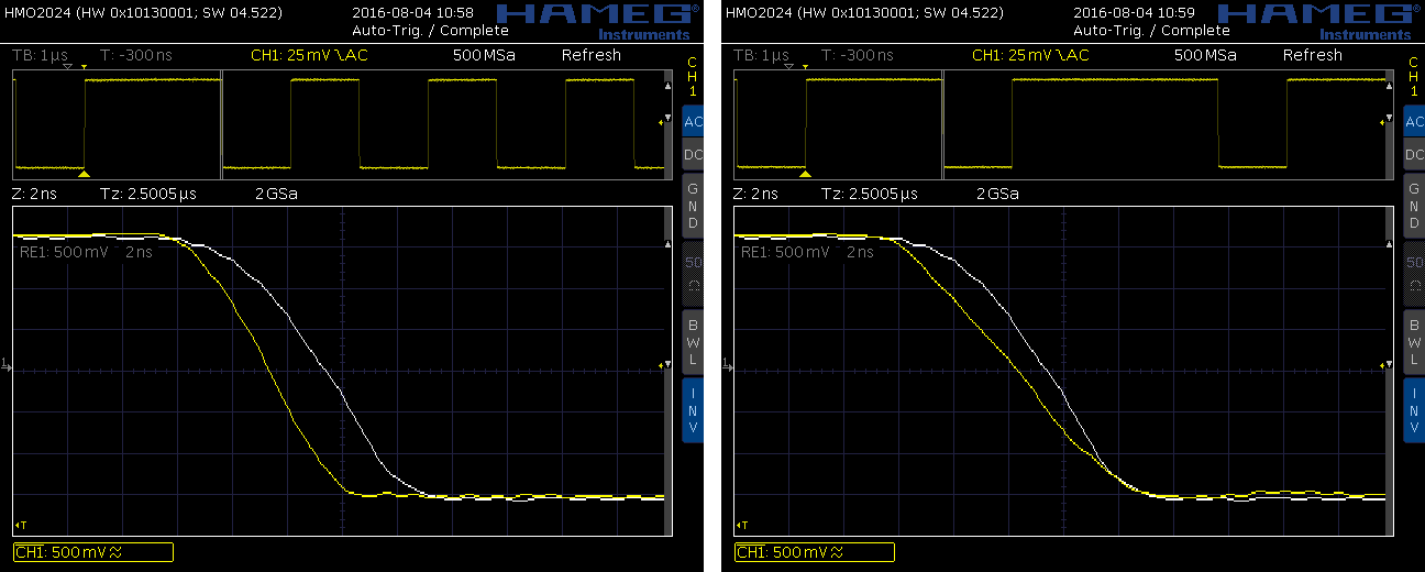 Though the µC's CMOS outputs are specified to be fully symmetrical, i.e., the pulldown FET is as strong as the pullup FET, it turned out that the signal's positive and negative slopes were not as equal as could be expected. Thus, the signal's average value becomes more positive the more slopes are present in the bitstream. This leads to slight distortions. In a certain amount this can be compensated by D2.1, R2.1 and C2.1.
The effect is shown in the oscillograms on the right: In both cases the scope was triggered on the (slower) negative slopes and the succeeding negative and positive slopes were displayed. For easier comparison, the positive slopes were displayed inverted.
The left oscillogram is uncompensated, the right one is compensated. With an additional delay the situation would become even better - maybe next time.
After all, I must admit that the expected reduction of the dominating 2nd harmonic wave was minimal, less than 0.5 dB. Bad luck. Something else creates much more of that distortion.
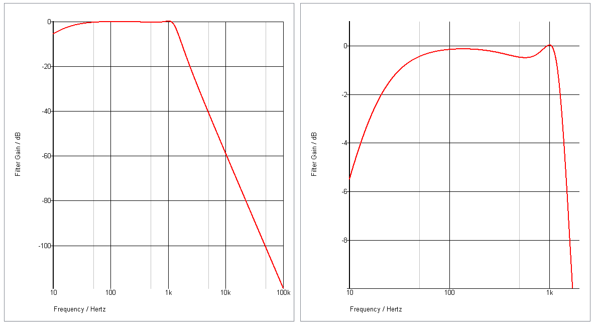 A low-pass filter is needed to remove the quantizing noise of the bitstream. This filter is a single stage, 3rd order 0.5 dB Chebycheff LPF. It is dimensioned so that even slight frequency changes, e.g., due to component tolerances or thermal drifts of the capacitor values, do not harm much because the nominal frequency of 1 kHz is just on the horizontal section of the Chebycheff maximum. As at 1 kHz the filter's gain is very close to 1, (theoretically 0.021 dB = 1.0024), at the filter's output again a sine wave amplitude of 1.05 VRMS appears.
It wouldn't make much sense to use ordinary filter capacitors with tolerances of 10% or even more here. Or, vice versa, all these thoughts wouldn't make much sense when such capacitors would be used. Thus I used 1% WIMA FKP (polypropylene) capacitors.
As I don't rely on the resistor's precision, I made each divider setting adjustable. The generator is built to calibrate studio equipment, so no specific voltages but some standard studio signal levels in dBu can be selected. The relations between the dBu settings and the corresponding voltages are indicated in the circuit diagram.
The potentiometer's output voltage is amplified and adjusted by R4.9 so that in the 100% position the positive line of the balanced output signal is exactly 5 VRMS. Then the negative line is adjusted by R4.4 to exactly 5 VRMS, too. Finally all dBu settings are adjusted for the correct voltages.
The balanced output is a push-pull output, i.e., it is not floating against the internal ground. It's output impedance is very low so that the load impedance of connected devices under test do not change the output voltage. Consequently in case of overload the output current can become quite high, just limited to up to 40 - 50 mA per op-amp output by the internal current limiting circuitry of the OPA2134. In order to ease that and protect the op-amps, they are supplied via 2 resistors (R1.1 and R1.2) and 2 capacitors, so that their power supply voltages decrease when high currents flow. As a consequence the output must not be loaded by too low impedances because it cannot supply the full output voltage at high currents any more. The limit is approx. 1 kΩ for an output voltage of 10 VRMS. Constant current sources instead of simple resistors would be better, of course.
 Though the generator is predominantly meant for level calibration I also laid an emphasis on a decent THD and noise. With an approximate THD of -82 dB = 0.008% it is not brilliant, but not bad either. In the spectrum above 50 kHz a remaining quantizing noise caused by residual tones (see below) is visible. But the oscillogram is clean, of course.
I made the spectrum measurements with my AD24QS, DA2USB on Windows 10 and a demo version of the Arta software.
The MSP430F2011 is a simple and cheap 16 bit µC. The only task running on it is to generate the bitstream for the 1 kHz sine wave signal. The code is written in Assembler and the correct output timing is achieved by exact cycle counting and adjustment ("NOP-stuffing").
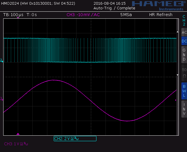 On the right you can see the µC's bitstream output (3.3 VPP) along with the successive low-pass filter output (2.8 VPP).
I provided two algorithms for generating the bitstream: Direct bitstream table lookup and sine wave table with a delta sigma modulator. Both are still available in the current code, but the latter is the only one used here.
The direct bitstream table lookup consists of 5 pre-calculated tables of 125 byte each = 1000 bit for each table. 1000 bit within 1 ms means a bitstream clock frequency of 1 MHz. Each of these 5 tables provides one full sine wave for one specific amplitude. With these 5 tables I originally intended to avoid an analog level divider and switch, but finally I didn't use this method.
For the sine wave table with a delta sigma modulator method also 5 pre-calculated tables are provided, also for different amplitudes, but for a different reason. Each table contains 400 16 bit words for one half sine wave only, so that one full sine wave consists of 800 values. The delta sigma modulator is operating at 800 kHz so that it can use for each operation the table's values consecutively.
The reason for the 5 tables here is an effect of delta sigma systems that (probably not only) I call the residual tones. They do not only, but predominantly appear at output levels close to the limits. When the average value of a bitstream comes close to the positive or negative rail, some noise appears more and more in the spectrum's band of interest. In 1st order modulators this noise is a single tone. In order to avoid that, it is advisable not to use the full scale range. Which range is actually advisable is a matter of compromises. Thus for experiments I provided these 5 tables with peak values of 80, 85, 90, 95 and 100% amplitude. Finally I made my choice for the 90% table.
BTW: 90% means from 5% to 95% full scale. 5% means that the bitstream is 5% high and 95 % low, or 1 out of 20 bits is high. When 1 out of 20 bits is high and the clock frequency is 800 kHz, this high-bit appears with a frequency of 40 kHz. Thus residual tones down to 40 kHz can be expected - now look at the spectrum above and what do you see there?
You can find more information about delta sigma conversion, bitstreams and the residual tone issue in my article "An Introduction to Delta Sigma Converters".
I don't offer DIY kits, PCBs or components. I hardly expect interested DIYs - this device is too exotic. But it is designed using THT-devices and thus not too difficult to rebuild. Only the 16 MHz oscillator and the ADR4533 are available as SMDs only so I mounted them on adapter PCBs.
I neither publish the Gerber/Excellon files nor the µC's source codes or hex files here. Nevertheless, should you want to build this generator or just use the µC as a sine wave source or even just be curious, let me know. But please excuse that I don't have a BOM with all details and sources.
The processor can be programmed and even run on the cheap TI Launchpad MSP-EXP430G2.
| Last update: August 6th, 2016 | Questions? Suggestions? Mail Me! | Uwe Beis |